User Interface
The software UI consists of several sections:
- Printable space: White gridded center.
- Action Bar: Horizontal bar across the top.
- Menu List: Button in the top-left corner.
- Tool Bar: Vertical bar on the left side.
- Print Menu: Printer icon in the top-right corner.
- Parts List: List icon under the Print menu.
Menu List
Press the icon to open this Menu.
| Command | Description | Shortcut |
| New | This command opens a dialog box to create a new project, choose recent files to be opened, or watch the software tutorials. | — |
| Open | This command opens a dialog box to load files. | Ctrl + O |
| Recent files | This command opens a dialog box to load the most recently opened files. | — |
| Recent jobs | This command opens a dialog box to load the most recently saved/sent to printer job files. | — |
| Save | This command saves the last changes made to the project files. | Ctrl +S |
| Save As | This command opens a dialog to save a new project file to a specified folder. | Ctrl+Shift+S |
| Print Job Report | This command opens a dialog to save your job report. | — |
| Calibrate Printer | This option allows you to calibrate your printer to increase its printing precision. | — |
| Preferences | This command opens a dialog to choose the projection type, measurement units, scroll direction, automatic placement, interface language, and shortcuts info. | — |
| Help | This command redirects you to the company’s website support section. | F1 |
| What’s New? | This command opens a window for checking the latest changes to your software version. | — |
| Check for Updates | This command checks for the available software updates. | — |
| Activate License | This command allows you to activate a License or request a Trial version. | — |
| Feedback | This tool allows you to send your feedback, report a problem, or submit a suggestion. | — |
| About | This command opens the dialog box displaying the software's version number and release date. | — |
| Exit | This command shuts down the software. | Ctrl + Q |
Tool Bar
This menu is located on the left side of the screen and displays basic editing functions.
| Command | Description | Icon |
| Parts Queue | This parameter allows you to monitor folders within your network and load files automatically for further processing, see Parts Queue. |
|
| Size | This command shows options for scaling a part, see Change Model Size. |
|
| Orientation | This command shows options for a part orientation, see Orient Model. |
|
| Labeling | This command shows options for creating and placing a label on the surface of a part, see Label Model Manually and Label Model Automatically. |
|
| Supports and Base | This tool allows creating supports for a part without using an external program, see Auto-Generate Supports and Add Supports Manually. |
|
| Layout | This command shows options for a part positioning and placement, see Position Model. |
|
| Base Tools | This tool allows for tuning up the parameters dedicated to working with lower layers of models, see Apply Base Tools. |
|
| Offset | This tool corrects dimensional inaccuracies by adjusting the model, compensating for inner structure shrinkage and outer structure expansion, see Offset. |
|
| Autopilot | This tool performs auto placement of parts and generates supports, see Autopilot. |
|
Print Menu
This menu is located in the top right corner of the app and is used as the final step to send the prepared model for printing, see Printing.
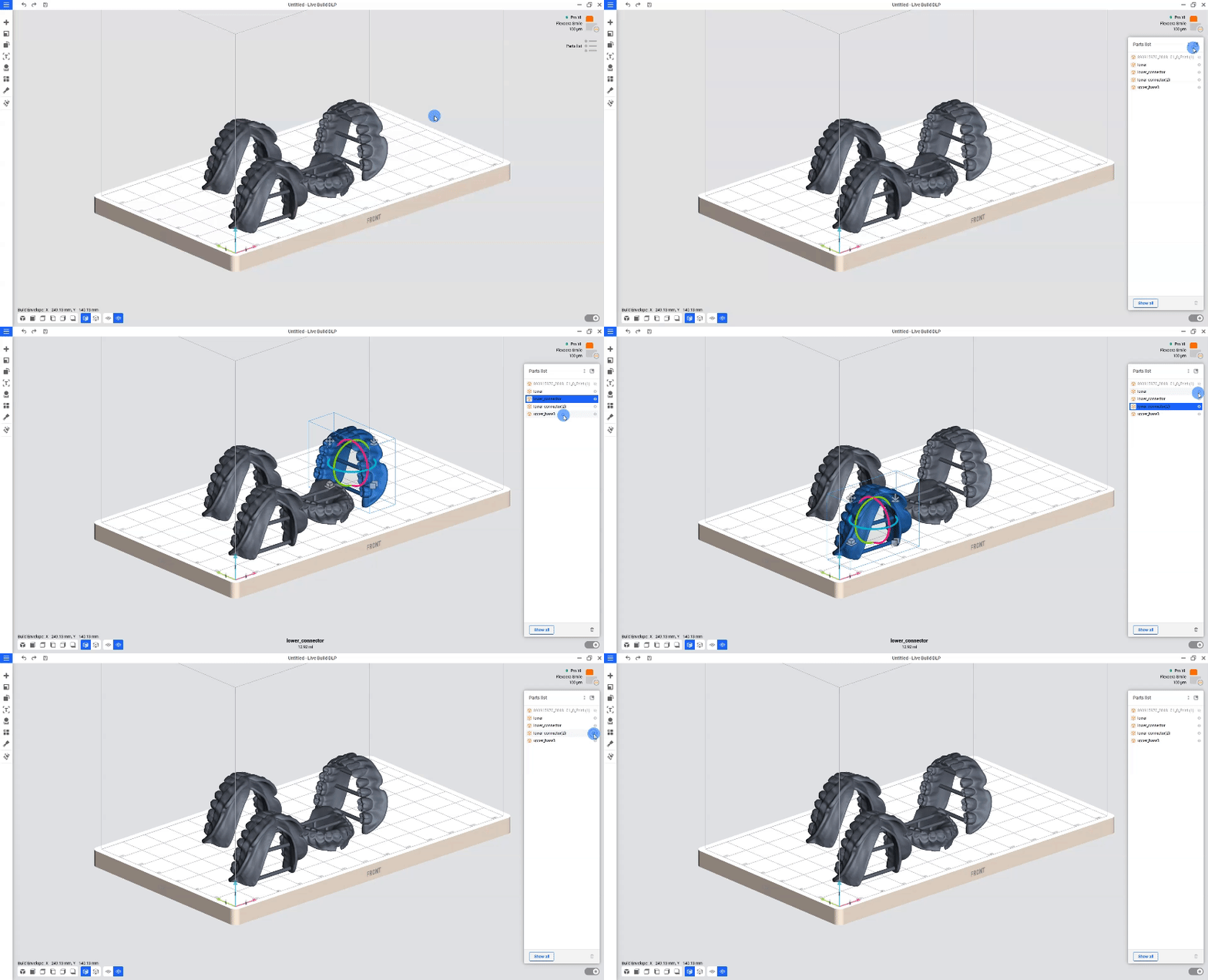
Parts List
The Parts list is located on the right side of the screen under the Print menu. It shows the list of models added to the project, allowing you to manipulate them individually without any dependencies or simultaneously. You can select multiple models, show or hide models within your workspace, and delete multiple models simultaneously.

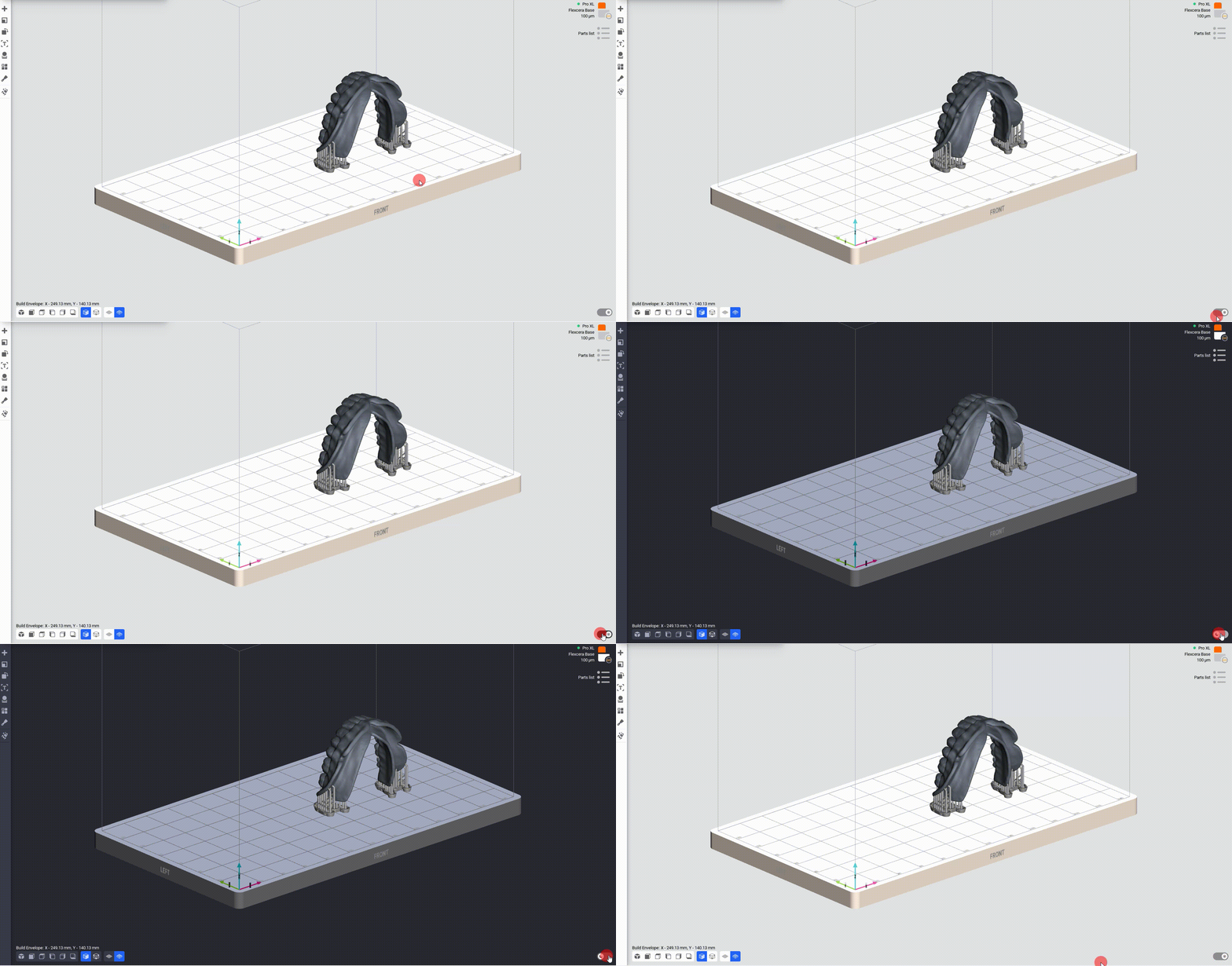
Dark Theme
With one ON/OFF button located in the lower right corner of the app, you can switch between light and dark modes.

Enable Freeform Rotation
-
Load a model into the scene.
-
Navigate to
> Preferences.
-
Set the Enable freeform rotation to Enabled and select Apply.
→ The Preferences window closes, and the gizmo sphere appears, allowing freeform rotation.